Ethohydraulic Research
Two sets of sensors will be developed during the project period. The first is a non-invasive biologger system, called backpack sensors, attached to the dorsal fin of fish weighing 3-5 g and measuring 25x14x4 mm (LxHxW). Comparative tests showed little change in swimming ability and negligible change in downstream passage time for rainbow trout greater than 250 mm body length. The sensors record pressure, accelerations, and orientation at up to 2048 Hz. This allows detection of barotrauma risks, but more importantly for tracking swimming activity and collisions. RETERO backpack sensors are perfectly suited for both hydropower and ethohydraulic studies, providing new and important insights into aquatic passage behavior. First tests with eels and roach were conducted in a large Archimedean screw in Belgium and showed significant behavioral effects and differences when comparing passive and fish mounted sensors.
RETERO Flume
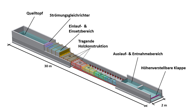
The ethohydraulic experimental flume has a total length of L = 30.0 m and consists of 4 sections. The first section, constructed of concrete elements and masonry, comprises the filling tank, in which the flume can be fed with flows of up to Qmax = 500 l/s, and a flow straightener. The adjoining second section was constructed with hard foam panels and has a width of B = 2.0 m. It is also used during the fish tests. It serves as an insertion area during the fish tests. The third section is the heart of the model test. Starting here, the channel changes from an open to a closed channel. The pressure tunnel, made of Plexiglas on a wooden construction, has a length of L = 12.5 m. On the first 7.5 m, the width narrows linearly from W = 2.0 m to W = 0.45 m. The further 5.0 m of closed channel then again have a constant width of W = 0.45 m. This third section has a slope of 1.67% and serves as an observation area during the fish tests. The fourth and last part of the channel is designed as an open, 2.0 m wide channel (concrete and masonry) and is closed by a height-adjustable flap. The latter can be used to regulate the water level in the model. Furthermore, disturbance elements are installed here, which reduce the flow velocity again. A rake serves as an obstacle for the descending fish, so that they cannot reach the deep reservoir of the laboratory via the flap. The test animals are removed in front of the rake after successful descent.
The selected geometry of the pressure tunnel leads to a continuous acceleration of the flow in the first, tapered part, so that ultimately, depending on the set flow rate, flow velocities in the range of the maximum sprint velocity of the fish are achieved in the constant-width part.
In addition to investigating fish responses to described longitudinal gradients, a transverse gradient can be generated in the front section of the pressure tunnel by installing a baffle in the insertion area. Furthermore, a sill closed part of the flume was used for the experiments with perch in fall 2022, which creates a clearer zonation of the spatial velocity gradient in the flow direction.
The entire model can be completely darkened thanks to an enclosure, so that night conditions can be simulated in addition to daylight conditions.

3D video tracking system
To record the fish behavior, the observation area was divided into 5 so-called arenas (each L = 2.5 m). For each of the arenas A1 to A4, one camera was positioned above the channel and one camera at the side, so that a three-dimensional evaluation of the fish paths can be carried out. In the second project phase starting in 2022, the tracking system was expanded to include Arena A0 (Fig 1.). Because the first 2.5 meters of the pressure area cannot be seen from the side due to a concrete element, this area was equipped with 2 additional cameras at least from above.
To generate usable video recordings, the channel must be illuminated in such a way that the fish body can be recognized even in night conditions. For this purpose, an illumination system consisting of an IR illuminator array was developed.
This has the advantage that the selected wavelength is in the non-visible range of the fish and thus does not influence their behavior. To ensure that the fish can be seen as a dark silhouette against a uniformly bright background, the Plexiglas walls illuminated by the IR array were equipped with diffuser foils. (Fig. 2) During the fish tests, the video recordings are started automatically and synchronized afterwards with the help of IR link signals. Simultaneous magnetic pulses from a coil can also synchronize the backpack sensors with the tracking data.
![]()
![]()
Hydraulic measurements
To describe the channel hydraulics, physical measurements were made on the model by IWD in addition to the numerical simulation by ISUT. Eight cross sections in the observation area were measured with a 2D laser Doppler anenometer (TSI) at high resolution (Fig. 3). ADV measurements (Nivus wedge sensors & Vectrino) were taken for the hydraulics of the hypothesis with baffle. During the fish tests, the model inflow (MID), as well as the water levels (ultrasonic probes) in the insertion and removal area are continuously recorded.


